Loading...


Search for
Search

PANAM VALVES
Precision-engineered instrumentation solutions for critical global infrastructure.
Headquarters
Ground Floor, St Edburgs Hall
Priory Road, Bicester, OX26 6BL
United Kingdom
© 2026 Panam Valves Ltd. All Rights Reserved.
Smarter Instrumentation: Choosing the Right Manifolds for Accurate, Safe Measurement
Comparing 2-, 3-, and 5-Valve Configurations, Monoflanges, and Integral DB&B — What to Choose and Why
SK
Steven Kassi
SEO Expert
May 25, 2026 • 8 min read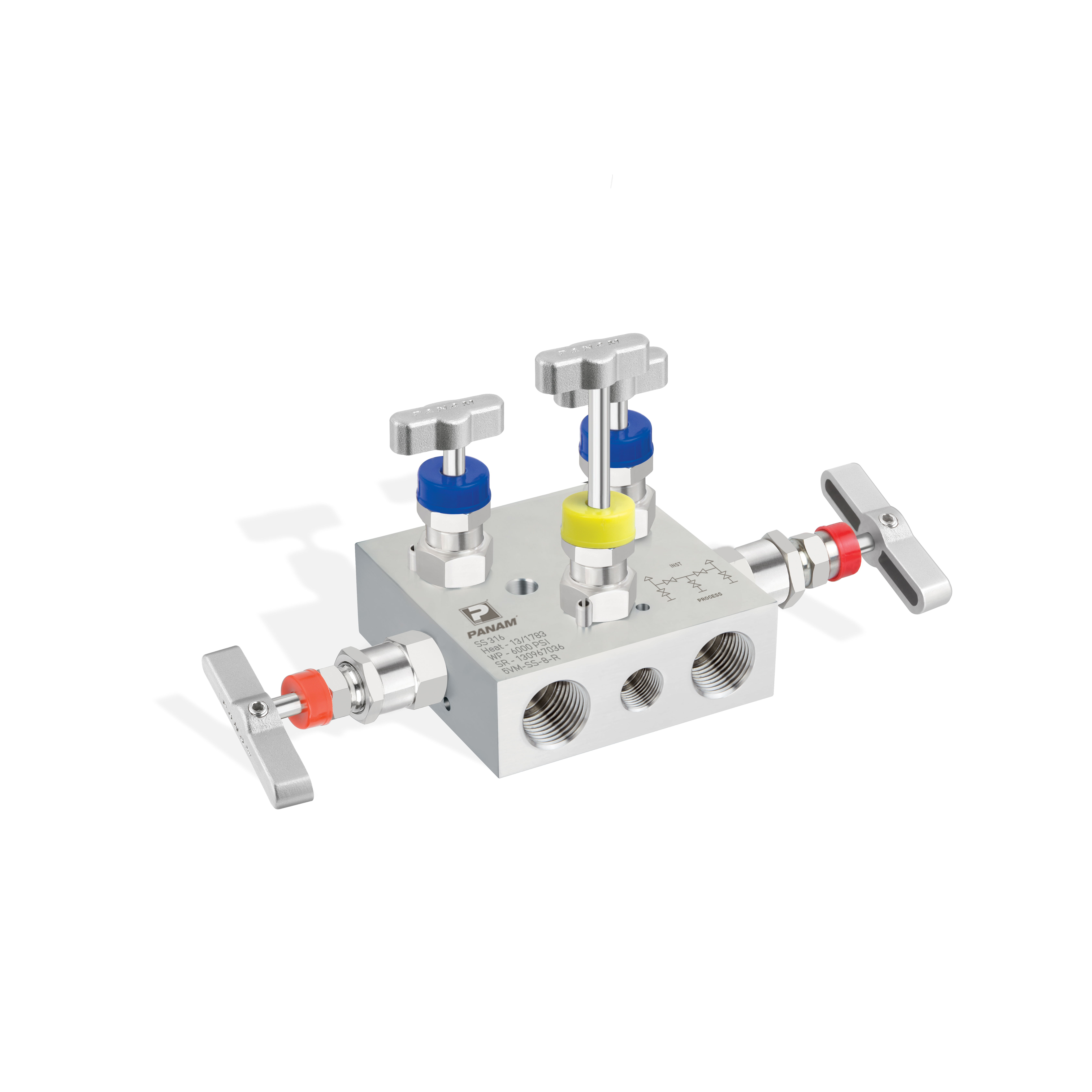
Measurement reliability lives or dies in the last few inches before the transmitter. Choose the wrong manifold architecture and even the best sensor will drift, plug, or read the process instead of the impulse line. Choose well and you improve accuracy, reduce leak paths, and cut maintenance hours across the year.
This guide compares common manifold configurations and installation practices that improve differential pressure (DP) flow, level, and pressure measurements. It also highlights hydrogen and gas-specific nuances, and where integrated solutions can reduce your bill of materials and time on site.
What Is a Manifold Valve and Why Does It Matter?
A manifold valve is a compact assembly that combines multiple valve functions into one block to connect a process to an instrument. Instead of separate root valves, isolation valves, equalising paths, and vents, a manifold centralises these functions with machined internal passages and integrated needle valves.
How it works in practice:
• Isolation valves open or close the paths from the process to the transmitter.
• An equalising valve balances high and low sides on DP transmitters to protect the sensor and enable zeroing.
• A bleed or vent provides a safe point to depressurise or remove trapped gas or liquid before maintenance or calibration.
The purpose in piping is simple but critical: provide controlled, leak-tight isolation and conditioning of the medium right where the measurement is taken, while reducing fittings, joints, and potential leak points.
Comparing 2-, 3-, and 5-Valve Manifolds
The right manifold type depends on your measurement duty, how frequently you calibrate or purge, and how much isolation assurance the service demands.
| Type | Isolation Valves | Equalising | Bleed Valves | Best For | Note |
|---|---|---|---|---|---|
| 2-Valve Manifold | 1 | — | 1 | Simple gauge / absolute pressure | Isolation plus controlled bleed for service |

| 3-Valve Manifold | 2 (H + L) | 1 | — | DP flow and level (workhorse) | Safe zero checks; protects sensor during commissioning |
| 5-Valve Manifold | 2 (H + L) | 1 | 2 (independent) | Frequent purging, calibration, gas service | Independent vents each side without disturbing the other |
Choose the fewest valves that still cover commissioning, proof testing, and routine maintenance. Every unnecessary port adds potential leak paths and operator complexity.
Monoflange vs Traditional Manifold Assemblies
Traditional builds use a separate root valve at the process take-off, then impulse lines, then a remote manifold. A monoflange integrates the root isolation and manifold functions into a single compact body that bolts directly to the process nozzle or instrument connection.
Monoflange advantages:
• Fewer threaded joints and gaskets, which lowers leak probability.
• Shorter swept volume between process and transmitter, improving dynamic response and reducing temperature or density stratification errors.
• Faster isolation and venting during maintenance.
Traditional assemblies remain useful where space is ample, retrofits must align with existing spool pieces, or where specific valve types are mandated. For greenfield projects or brownfield upgrades targeting reliability, monoflanges typically deliver better measurement integrity and reduced installation time.
Root Valves and Integral Double Block and Bleed
The root valve is the primary isolation at the process. Integrating root isolation with a double block and bleed (DB&B) function at the manifold provides positive isolation and a local vent for safe proving.
Benefits of integral DB&B manifolds:
• Positive isolation during maintenance or transmitter swap-out.
• A defined bleed path that supports pressure verification and gas-free work.
• Reduced parts count compared to separate ball valves, check valves, and tees.
Use integral DB&B on critical services, high-pressure gas, hydrogen applications, and any loop requiring a formal isolation and verification step. Explore PANAM's range of manifold valves and DB&B configurations for safe isolation, equalisation, and venting in compact, precision-machined bodies.
Hydrogen and Gas Measurement Nuances
Hydrogen and light gases raise specific concerns that standard manifold selections do not automatically address.
Diffusivity and measurement lag
Low density and high diffusivity increase the risk of measurement lag from trapped pockets and amplify the impact of even small leaks.
Pulsation bias
Pulsation from compressors or control valves can bias DP and gauge measurements. Consider pulsation dampening where relevant.
Material and seal selection
Permeation and embrittlement risks steer material and seal choices. Use hydrogen-qualified materials and seals throughout the manifold assembly.
Minimise impulse line length with close-coupled mounting. Compact monoflanges and transmitter-direct manifolds cut volume and thermal gradients. For hydrogen service, PANAM provides hydrogen-qualified valves and components designed for these demands.
Installation Best Practices That Protect Accuracy
Orientation and impulse lines
Keep the transmitter as close as practical to the take-off to shorten lag and reduce stratification. For gas service, mount taps above the line to avoid liquid pooling; for liquid service, mount below to prevent gas entrapment. Maintain consistent elevation between high and low sides on DP services and slope lines to encourage self-draining or self-venting.
Vent and bleed routing
Provide a safe, directed vent path. For hydrogen and flammable gases, route bleeds to a safe location — not to atmosphere at the instrument. Use dedicated bleed valves on 5-valve designs when frequent purging or calibration is expected.
Cold and hot service
Hot service can introduce density shifts and thermal expansion. Insulate impulse lines when required and avoid dead legs. Cold service can increase viscosity or cause condensation — use heat tracing or compact runs to maintain stable conditions.
Pressure class, materials, and seals
Select pressure ratings aligned with the highest credible pressure, including over-pressure scenarios. Favour stainless steel for general corrosion resistance. For hydrogen, use proven alloys and seal materials compatible with permeation and embrittlement. Keep one material family where possible to limit galvanic effects and simplify spares.
Connections
Use high-quality tube fittings and weld fittings on small-bore instrumentation. Minimise adapters and unions to reduce leak paths. For direct process connections, match the flange or threaded standard specified for the nozzle or tapping point.
Close-Coupled Mounting for DP Flow, Level, and Pressure
DP flow
A 3- or 5-valve manifold mounted directly to the transmitter shortens the impulse volume between high and low sides. Combine with a monoflange at the take-off to compress the entire assembly and improve response to flow changes.
DP level
Maintain equal elevation and short impulse runs. The equalising valve on a 3-valve manifold simplifies zeroing after shutdowns when legs may partially drain or gas up.
Gauge and absolute pressure
A 2-valve block with bleed is often sufficient. In gas service, consider pulsation dampening and a short path to prevent dynamic measurement errors.
How to Install a Manifold Valve — Step by Step
1. Verify ratings and compatibility
Check pressure class, materials, and seal compatibility against the process medium and site standard before installation begins.
2. Inspect and protect sealing faces
Inspect sealing faces and threads; clean and cap until the moment of installation to prevent contamination.
3. Mount to the process take-off
Install the monoflange or root valve with the correct gasket and torque. Orient the vent toward a safe direction before tightening.
4. Install the manifold to the transmitter
Secure the manifold to the transmitter or bracket, confirming correct high/low port orientation against the P&ID.
5. Run and slope impulse lines
Keep lines as short as practical. Tighten tube fittings to specification and slope lines to encourage self-draining or self-venting.
6. Pressure and leak test
Pressure test to the approved test pressure; check all joints. Perform a functional leak check with the appropriate test medium.
7. Commission in sequence
Isolate, open equalising (for DP), slowly crack process isolation to fill lines, close equalising, then fully open isolations. Bleed trapped gas or liquid and verify zero.
Frequently Asked Questions
What is a manifold valve?
A multi-valve block that provides isolation, equalisation, and vent functions between a process connection and an instrument in a single compact body.
What are the benefits of a manifold?
Fewer leak paths, faster maintenance, safer isolation and venting, and improved measurement stability through compact, well-controlled flow paths.
How does a manifold work?
Internal passages connect the process to the instrument through isolation valves, an equalising valve for DP service, and a bleed valve for safe depressurisation and purging.
What is the purpose of a manifold in piping?
To centralise control of the measurement take-off, enabling accurate, safe, and maintainable instrumentation connections with fewer fittings and joints.
How do you install a manifold valve?
Verify ratings and materials, mount to the process, connect to the transmitter, run and slope impulse lines, leak and pressure test, then commission using a controlled isolation and equalisation sequence.
Summary and Next Steps
Measurement reliability depends on the architecture directly upstream of the transmitter. Match the manifold type to the duty — 2-valve for simple pressure, 3-valve for DP, 5-valve where frequent purging or calibration is expected. Use monoflanges to cut joints and improve response. Specify DB&B where positive isolation is required, and apply hydrogen-qualified materials and seals on any gas or hydrogen service.
For help selecting the right manifold configuration or building a standardised package for your site, browse PANAM's full manifold valves range or speak to our team for application-specific guidance.
Planning mid-year maintenance or a metering upgrade where measurement accuracy matters?
Book a manifold standardisation workshop with PANAM. Our engineering team will align specifications, simplify your spares, and confirm the right manifold architecture — 2-, 3-, or 5-valve, monoflange or DB&B — so your instrumentation performs reliably from day one.
At a Glance
• What Is a Manifold Valve
• 2-, 3-, and 5-Valve Comparison
• Monoflange vs Traditional
• Integral DB&B
• Hydrogen & Gas Nuances
• Installation Best Practices
• Close-Coupled Mounting
• Step-by-Step Installation
PANAM Manifold Valves
2-, 3- & 5-Valve · DB&B · Monoflange · Hydrogen-Ready
Browse the range →