
Loading...
Technical Guide
3-Valve Manifolds Explained: How They Work, How to Operate Them and Why Readings Go Wrong
What the transmitter measures, what each valve does, the operating sequences, and a fault-finding guide for readings that look wrong.
SK
Steven Kassi
Technical Author
October 28, 2026 • 11 min read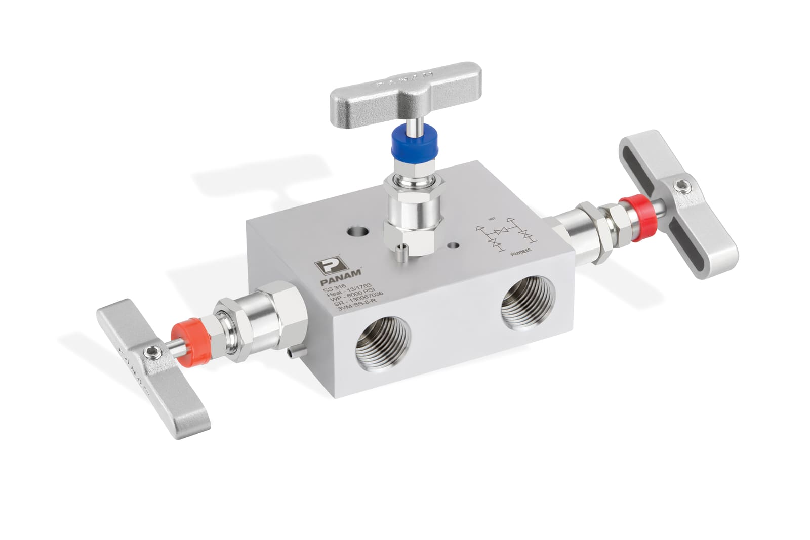
A differential pressure (DP) transmitter measures the difference between two pressures, often only a few millibar, while both sides sit at a much higher line pressure. A 3-valve manifold is the small valve block that lets you connect, check, zero and remove that transmitter without shutting the process down.
This guide explains what the transmitter actually measures, what each of the three valves does, and why the valves must be operated in a set order. It gives the sequences for putting a transmitter into service, checking its zero and taking it out of service, followed by a fault-finding table for readings that look wrong. It ends with what a manifold specification should state.
Key takeaways
- A DP transmitter measures the difference between two pressures that both sit at line pressure, so applying pressure to one side only can overrange the sensor.
- A 3-valve manifold has two block valves and one equalising valve. In normal operation the block valves are open and the equalising valve is closed.
- The equalising valve balances the two sides, so the zero can be checked under line pressure and the transmitter can be isolated without a one-sided pressure.
- Never leave the equalising valve open while both block valves are open. It connects the high and low impulse lines and the reading collapses towards zero.
- Many wrong readings come from the manifold or the impulse lines, not the transmitter: a leaking equalising valve, a shut or passing block valve, an open vent, a blocked or badly filled impulse line.
- Sequences vary by installation. Follow the transmitter and manifold manufacturers’ instructions and your site procedure.
What does a differential pressure transmitter measure?
A DP transmitter measures the difference between the pressure on its high side and the pressure on its low side. Both sides are connected to the process by impulse lines, so both sit at line pressure, and the transmitter reports only the small difference between them.
That difference is the signal in three common uses:
- Flow: the pressure drop across a primary element, such as an orifice plate, relates to the flow rate.
- Level: in a closed vessel, the difference relates to the height of liquid.
- Filter monitoring: the pressure drop across a filter shows how blocked it is.
Two consequences shape how a manifold is used. First, the sensor sees a small difference sitting on top of a much larger static pressure. As an illustration, a transmitter on a 100 bar line might be ranged for only a few hundred millibar. Applying line pressure to one side only can therefore overrange the sensor. Second, static pressure can shift a transmitter’s zero, which is why the zero is best checked with both sides at the same line pressure and not only on the bench.
The impulse lines are the tubes or pipes that carry process pressure from the tapping points to the transmitter. Depending on the application they may be filled with process fluid, with a fill liquid, or, in some level measurements, with a reference column known as a wet leg.
What is a 3-valve manifold, and what does each valve do?
A 3-valve manifold is a valve block that sits between the impulse lines and a differential pressure transmitter. It has a high-pressure block valve, a low-pressure block valve and an equalising valve. The block valves isolate the transmitter, and the equalising valve balances the pressure across it.
| Valve | What it does | Normal operation |
|---|---|---|
| High-pressure (HP) block valve | Connects or isolates the high-pressure impulse line | Open |
| Low-pressure (LP) block valve | Connects or isolates the low-pressure impulse line | Open |
| Equalising valve | Links the two sides of the transmitter so the pressure balances across it | Closed |
A 3-valve manifold has no vent of its own unless one is fitted. If you need to vent or drain the transmitter, for example to release trapped gas or liquid, check whether the manifold has vent or drain ports, or use a 5-valve manifold.
Why is there an equalising valve?
The equalising valve puts the same pressure on both sides of the transmitter. That makes three jobs safe: checking the zero under line pressure, bringing the transmitter into service without a one-sided pressure, and isolating it before removal.
In normal operation it must stay closed. With both block valves open, an open equalising valve gives the process a short path from the high side to the low side. Flow then bypasses the measurement, and the transmitter reads close to zero.
How do you operate a 3-valve manifold?
Open and close the valves in a fixed order, so the transmitter never sees a large one-sided pressure and the equalising valve is never open while both block valves are open. The sequences below are the ones most commonly published. Follow your transmitter and manifold manufacturers’ instructions and your site procedure.
Putting a transmitter into service
| Step | Action | Why |
|---|---|---|
| 1 | Confirm both block valves are closed and the equalising valve is open | Starts from a known state with both sides connected |
| 2 | Open the HP block valve slowly and check for leaks | Pressurises both sides equally through the equalising valve |
| 3 | Close the equalising valve | Locks the same pressure on both sides and separates them |
| 4 | Open the LP block valve slowly | Applies the low-side pressure, so the transmitter reads the working differential |
Checking the zero under line pressure
| Step | Action | Why |
|---|---|---|
| 1 | Close the LP block valve | Isolates the low side so equalising doesn’t open a path through the process |
| 2 | Open the equalising valve | Applies the same pressure to both sides, so the differential should be zero |
| 3 | Read the output. Trim the zero only after ruling out real causes | A non-zero reading can be zero shift, an installation effect or an earlier overload |
| 4 | Close the equalising valve | Separates the two sides again |
| 5 | Reopen the LP block valve slowly | Returns the transmitter to service |
Taking a transmitter out of service
| Step | Action | Why |
|---|---|---|
| 1 | Close the LP block valve | Isolates the low side |
| 2 | Open the equalising valve | Balances the pressure across the transmitter |
| 3 | Close the HP block valve | Isolates the transmitter, which can now be vented, calibrated or removed |
Three rules apply whatever the sequence: never open the equalising valve while both block valves are open; open valves slowly, so no sudden differential reaches the transmitter; and don’t re-zero without checking why the reading isn’t zero. A shifted zero after an overload or after pressurising can mean the sensor needs checking, not just trimming.
Where procedures differ
- Level measurement with a wet leg. Opening the equalising valve can push liquid out of the reference leg, so check your procedure before zeroing.
- Steam and condensate duty often has its own site procedure. Follow it.
- 5-valve manifolds have two equalising valves and a vent, so the order changes (see below).
What changes with a 5-valve manifold?
A 5-valve manifold adds a second equalising valve and a vent valve to the 3-valve arrangement, so the two sides can be balanced in stages and the transmitter vented. It is commonly specified for gas metering.
With two equalising valves, open the high-pressure one first. Opening the low-pressure one first can overpressurise the transmitter. When you finish, close them in the reverse order, low-pressure first.
| Manifold | Valves | Typical use |
|---|---|---|
| 2-valve | One block valve and one bleed (vent) valve | Isolating and venting a single-pressure instrument |
| 3-valve | Two block valves and one equalising valve | DP transmitters: isolation, equalisation and zero check |
| 5-valve | Two block valves, two equalising valves and one vent valve | DP measurement where a second equalising valve and a vent are specified, such as gas metering |
For a comparison of manifold configurations and mounting styles, see our guide to choosing the right instrument manifold.
Why do DP readings go wrong?
Many wrong DP readings come from the manifold or impulse lines rather than the transmitter. Common causes are an equalising valve that is open or leaking, a block valve that is shut or passing, an open or leaking vent, a blocked impulse line, and gas or condensate in the wrong place.
| Symptom | Likely cause | What to check |
|---|---|---|
| Reading near zero, or lower than expected, while the process is flowing | Equalising valve open, not fully seated, or leaking | Confirm it is fully closed, and check the manifold for tightness |
| Reading doesn’t respond to process changes, or is stuck or noisy | Blocked or partly blocked impulse line, for example from deposits or, in cold service, freezing | Check that the line is open end to end |
| Reading looks one-sided or doesn’t match the process | LP block valve shut or partly shut | Check the valve positions |
| Reading fluctuates or drifts | Vent or drain open or leaking; gas bubbles in a liquid-filled line, or condensate in a gas line | Check vent and drain valves, and vent or refill the impulse lines |
| Zero won’t settle, or pressure doesn’t equalise cleanly | A block valve passing, or trapped pressure | Check both block valves are fully closed during the zero check, and check the manifold for tightness |
| Zero has shifted after pressurising | Static pressure effect, installation position, or an earlier overload | Check the zero under common line pressure, and rule out an overload before re-zeroing |
| Transmitter can’t be isolated for removal | A block valve not sealing | Treat the line as live and follow your site isolation procedure |
| Leak at a stem or thread | Worn packing, or a damaged seal washer or thread seal | Follow your site procedure before attempting any repair |
These are common causes, not a complete list. Always rule out a real pressure difference in the installation before concluding the transmitter has drifted.
Which manifold suits which job?
| Scenario | Typical manifold | Notes |
|---|---|---|
| DP flow measurement across an orifice plate | 3-valve. A 5-valve manifold if your specification calls for two equalising valves and a vent, as in gas metering | Confirm the impulse-line arrangement and the pressure first |
| DP level measurement in a closed vessel | 3-valve | With a wet leg, check the zeroing procedure first. Add vent or drain ports if the transmitter must be vented for calibration |
| Filter or strainer monitoring | 3-valve | Equalise before isolating, so the transmitter never sees a one-sided pressure when you service it |
| Single-pressure (gauge or absolute) transmitter | 2-valve block and bleed | A 3-valve manifold is the wrong configuration |
| Sour gas service | 3-valve in materials qualified for H2S service | State the H2S conditions and the edition of NACE MR0175 / ISO 15156 your project specifies |
| High-pressure systems | A manifold rated for the system pressure | Check that the transmitter, tubing and connections are rated for the same pressure |
| High or low temperature service | A manifold suited to the temperature range | State the minimum and maximum temperatures in the specification |
| Field zero check and calibration | 3-valve with vent or drain ports, or a 5-valve manifold | Isolate, equalise, then vent following your procedure |
What should a manifold specification include?
A manifold specification should state the transmitter and mounting, the configuration, the pressure and temperature, the media, the materials, the connections, the options, the tests and the documents. Remember that the system is limited by its lowest-rated component, so the transmitter and connections matter as much as the manifold.
| Item | What to state | Why it matters |
|---|---|---|
| Transmitter | Make, model and mounting (direct-mount or remote) | Sets the interface the manifold must match |
| Configuration | 2-, 3- or 5-valve, and whether vent or drain ports are needed | Defines the valve arrangement |
| Pressure | Maximum working pressure and design pressure | Sets the manifold rating |
| Temperature | Minimum and maximum, including ambient | Affects materials and seals |
| Media | Fluid, composition, and any H2S or CO2 | Decides whether sour-service materials are needed |
| Materials | Body, seat and packing materials, and the NACE edition if sour | Matches the media and the standard |
| Connections | Process connection type and size, and the transmitter-side interface | Avoids mismatched threads or flanges |
| Testing | Pressure tests and acceptance levels, and any fugitive emissions class | Defines the inspection scope |
| Documentation | Certificate type, for example EN 10204 3.1 or 3.2, and traceability | Avoids rework at inspection |
Which standards can apply?
These standards can apply to a 3-valve manifold, depending on your project specification.
| Standard | What it covers | When it matters |
|---|---|---|
| IEC 61518 (EN 61518) | Mating dimensions, tolerances, threads, bolts and gaskets for a DP instrument with a manifold bolted directly on, for working pressures up to 413 bar at 38 °C. It does not apply where an adapter with extra sealing elements sits between them. | Direct-mount DP transmitters, within its pressure limit |
| NACE MR0175 / ISO 15156 | Selection and qualification of metallic materials for equipment in H2S-containing environments in oil and gas production and natural-gas sweetening plants. Not necessarily applicable to refining or other downstream equipment. | Any sour gas service. State the edition your project specifies |
| ISO 15848-1 | A classification system and type-test qualification for fugitive emissions from the stem seals and body joints of isolating and control valves. End connection joints are excluded. | Projects with a fugitive emissions requirement |
| BS EN 12266-1 | Production pressure tests (shell strength, shell tightness and seat tightness), test procedures and acceptance criteria for metallic industrial valves. | Where documented or witnessed pressure tests are required |
| EN 10204 | Types of inspection document for metallic products: 2.1, 2.2, 3.1 and 3.2. A 3.1 certificate is batch-specific and validated by the manufacturer. A 3.2 adds validation by a purchaser’s representative or an independent inspector. | Where material traceability is required |
Frequently asked questions
What is a 3-valve manifold?
A 3-valve manifold is a valve block that sits between the impulse lines and a differential pressure transmitter. It has a high-pressure block valve, a low-pressure block valve and an equalising valve. The block valves isolate the transmitter, and the equalising valve balances the pressure across it.
How does a 3-valve manifold work?
In normal operation both block valves are open and the equalising valve is closed, so the transmitter measures the difference between the two process pressures. Closing the block valves isolates it, and opening the equalising valve balances the two sides for zeroing or removal.
How do you operate a 3-valve manifold?
Use a fixed order. To commission, open the equalising valve, open the high-pressure block valve, close the equalising valve, then open the low-pressure block valve. To isolate, close the low-pressure block valve, open the equalising valve, then close the high-pressure block valve.
How do you zero a DP transmitter with a 3-valve manifold?
With the transmitter in service, close the low-pressure block valve, open the equalising valve, and read the output, which should be zero. Close the equalising valve, then reopen the low-pressure block valve. Rule out real causes of a non-zero reading before you trim the zero.
What is the equalising valve for?
The equalising valve puts the same pressure on both sides of the transmitter. That makes three jobs safe: checking the zero under line pressure, bringing the transmitter into service without a one-sided pressure, and isolating it before removal.
Why must the equalising valve be closed in normal operation?
With both block valves open, an open equalising valve connects the high and low impulse lines. Process then flows between the two sides, bypassing the measurement, and the transmitter reads close to zero differential pressure.
What is the difference between 2-valve, 3-valve and 5-valve manifolds?
A 2-valve manifold is a block-and-bleed for a single-pressure instrument. A 3-valve manifold adds a second block valve and an equalising valve for a differential pressure transmitter. A 5-valve manifold adds a second equalising valve and a vent valve, and is commonly specified for gas metering.
What causes a low reading on a DP transmitter with a manifold?
A common cause is an equalising valve that is open or leaking, which short-circuits the two sides. Others are a partly shut block valve, a blocked impulse line, an open vent, and gas or condensate in the wrong place. Check the manifold and impulse lines before blaming the transmitter.
Why equalise a differential pressure transmitter before isolating it?
Equalising removes the pressure difference across the transmitter before it is isolated. That protects the sensor from a large one-sided pressure, and makes it safe to vent or remove the instrument.
Which manifold do I need for a differential pressure transmitter?
A 3-valve manifold is the standard choice. Choose a 5-valve manifold if your specification calls for two equalising valves and a vent, as is common in gas metering. Use a 2-valve manifold only for single-pressure instruments.
Do I need a vent on a 3-valve manifold?
A 3-valve manifold has no vent unless one is fitted. If you need to vent or drain the transmitter to release trapped gas or liquid, specify a manifold with vent or drain ports, or use a 5-valve manifold, which includes a vent valve.
Which standards apply to a 3-valve manifold?
It depends on your project specification. Common ones are IEC 61518 for the direct-mount interface to a differential pressure transmitter, NACE MR0175 / ISO 15156 for sour service, ISO 15848-1 for fugitive emissions, BS EN 12266-1 for pressure tests, and EN 10204 for material certificates.
What is IEC 61518?
IEC 61518 specifies mating dimensions, tolerances, threads, bolts and gaskets for a differential pressure instrument with a manifold bolted directly to it, for working pressures up to 413 bar at 38 °C. It does not apply where an adapter with extra sealing elements sits between them.
In this guide
The one rule to remember
Never open the equalising valve while both block valves are open — it short-circuits the high and low sides and the reading collapses to near zero.